SANDING DEVICE WITH VARIABLE SAND FLOW
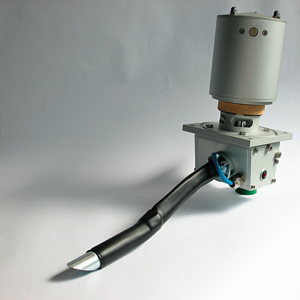 optimization of the consumption of sand and increase the effectiveness of treatment
- these are extremely compact devices containing inside all the elements necessary for sanding operation:
- magnet valve for sand jet
- magnet valve for sand fluidization and drying
- heating elements for the drying
- proportional dosing system
- sand level sensor
- the sanding of a bogie are connected to a logic unit installed on board the same. The logic unit is connected to the wiring of the body via a multipolar connection through which receives:
- the electrical supply
- the direction of travel
- the vehicle speed
- the command of sanding for both the braking and traction
- returns the functional status of each connected device
- via the same logic unit is also supplied the heater of sanding nozzle
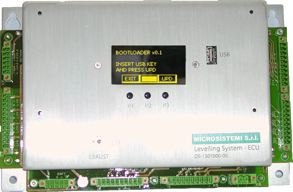
LEVELLING SYSTEM ECU FOR TRAMWAY LRV AND METRO
- 16 outputs for the control of magnet valves (maximum power 48W each) with diagnostics of:
- open circuit
- overloads
- hort circuit with protection
- 4 digital inputs galvanically isolated battery voltage
- 4 digital outputs galvanically isolated battery voltage 500mA or 2A
- graphical OLED display with extended temperature range (-40 to +85 ° C)
- USB interface to update the firmware via resident boot loader. The software allows a detailed diagnostics of whole leveling system components for quick commissioning and service
- power supply 24V +/- 30%
- EN501 55 compliant
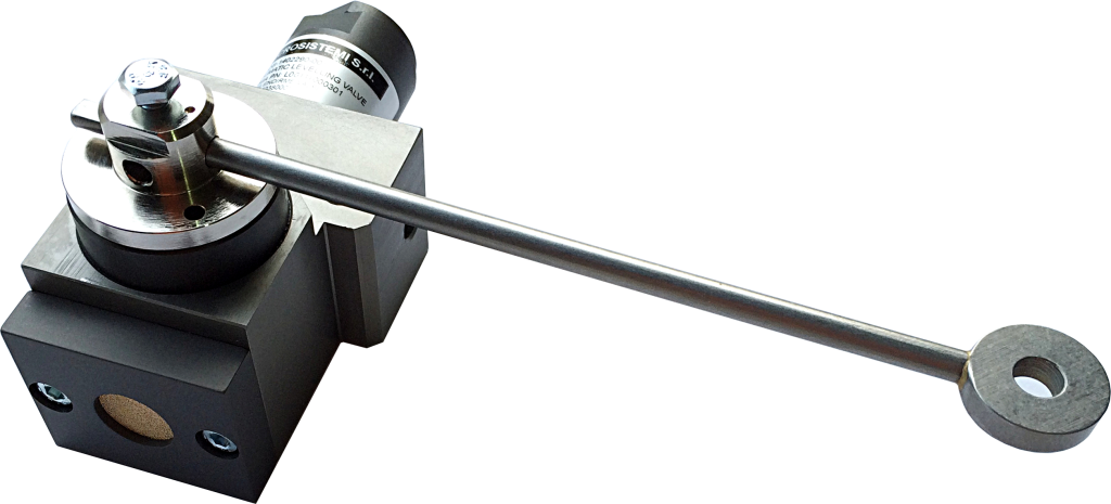
LEVELLING VALVE
RELIEF VALVE WITH WEIGHT TRANSDSUCER FOR TRAMWAY LRV AND METRO
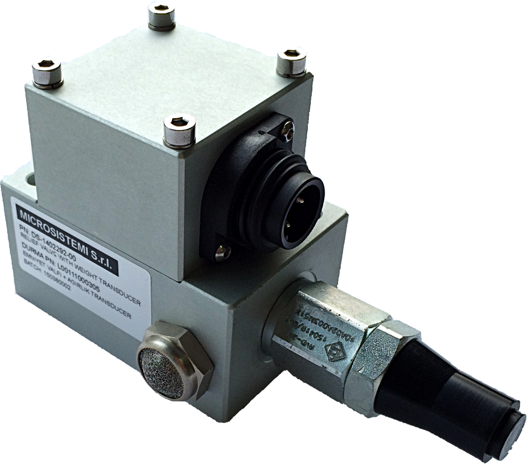 This device is a functional block that incorporates the pneumatics and the electronics. A pressure transducer is used, and then only one output is present to provide the weight information to the brake and/or traction systems. This output is a 4-20mA self powered
through the current loop.
FUNCTIONAL CHARACTERISTICS:
Operating pressure range 0-1 0 bar
Operating Temperature -40°C +85°C
Over pressure max. 20 bar
Burst pressure 35 bar
Accuracy (typ./max.) %FS 0.2/0.4
Thermal offset shift (typ./max.) %FS/K ± 0.005 / ± 0.020 25 – 85 °C
Electrical output 4 – 20 mA for 0 – 1 0 bar
OVERFLOW VALVE WITH DOUBLE WEIGHT TRANSDUCER
This device, in the solution proposed by Microsistemi, incorporates both functions: the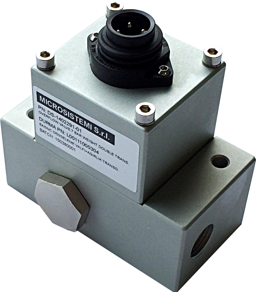
traditional pneumatics and, through two transducers, the electronic conversion of the
pressure values present in the air springs. The output signal is available for brake
system and/or traction on a 4-20mA channel. It is function of the average valve of both
pressures.
FUNCTIONAL CHARACTERISTICS
Operating pressure range 0-1 0 bar
Operating Temperature -40°C +85°C
Over pressure max. 20 bar
Burst pressure 35 bar
Accuracy (typ./max.) %FS 0.2/0.4
Thermal offset shift (typ./max.) %FS/K ± 0.005 / ± 0.020 25 – 85 °C
Electrical output 4-20 mA for 0-1 0 bar
the differential between the two pressures is adjustable on request.
DISPLACEMENT SENSOR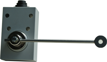
This devices has been studied to know the load variation due to different service conditions of a vehicle equipped with elastic element (like steel spring or rubber/steel spring) on the secondary suspension.
The Displacement Sensor checks the length of the secondary suspension element and gives an electrical signal proportional to that length.
The output is a 4-20mA current loop.
ON BOARD MODULAR INTERCOM SYSTEM FULL DUPLEX
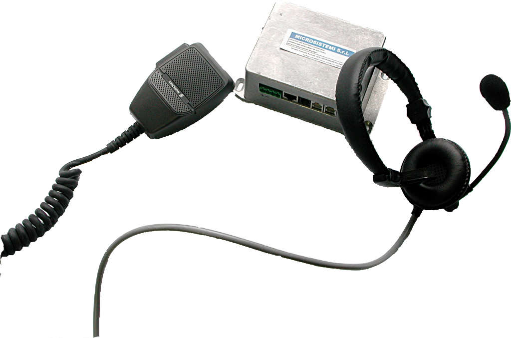 The system is based on a ” backbone “, consisting of a 600 Ohm two-wire line, that runs through the vehicle and whole train through the couplers. In series, along the same, are inserted the intercom units that have two connectors for this purpose. The system works in base band.
- each intercom unit performs a number of functions:
- bidirectional amplifier of the signals in transit on the line so as to maintain a constant level regardless of the length of the line itself due to the different configurations that can take the train
- locally derive the audio signal present on the line to send , after amplification, to loudspeaker or headset
- inject on the line the audio signal acquired locally through the microphone avoid that the signal of the local microphone has been reproduced from the local loudspeaker
- both connections to the 600 Ohms lines are galvanically isolated between them and also from the supply and from local circuits in order to avoid dangerous current loop return
- EN50155 compliant
MOTOR BRUSHLESS INVERTER FOR HPU FOR BRAKING SYSTEM
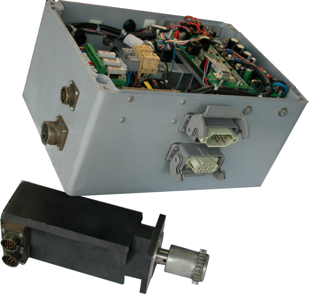 power up to 1.5 kW to the pump
- DC 24, 48 or 72 VDC
- possibility of using both motors with and without sensors
- closed loop pressure regulation through pressure transducer
- digital inputs for reading:
- level sensor
- pressure switch
- digital outputs for interfacing with the BCU
- data connection for configuration functions and / or diagnostic
- optionally filtered output for long wiring between ecu and motor
- EN50155 compliant
COMPACT HYDRAULIC POWER UNIT WITH ELECTRONIC CONTROL: BRAKE SYSTEMS AND LEVELLING SYSTEMS
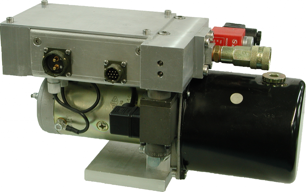 closed loop operation for the adjustment of the pressure controlled by an external analogic signal (eg 4-20 mA or 0-10V)
- maximum outlet pressure 130 bar, maximum working pressure is software selectable via the setup function
- 24 Vdc power supply (other voltages on request)
- serial connection for diagnostics and configuration control
- electronics and power fully integrated within the control unit
- soft start to prevent inrush current
- available with both motors with brushes and electronically commutated brushless
SPLITTED VOLTAGE TESTER ON STATIC CONVERTER FOR RAILWAY APPLICATION
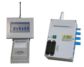 the apparatus consists of two interconnected units via radio frequency link:
- the acquisition unit , which is installed inside the box of the converter, is connected by means of wires with clips to the salient points of the semiconductor in question, after that the box can be closed to allow normal operation of the converter
- man / machine interface unity with graphical display and keypad for operating modes selection
- the instrument allows the measurement of the splitted input voltage up to 4Kv on the components (transistors or SCR) that, placed in series, constitute the converter switching groups. During the phases of non-conduction performed with the converter in service, the distribution measurement of the voltage across each device gives the effective state of efficiency of the devices themselves
- thanks to radio frequency link between acquisition unit and control display unit, the operator is in absolute safety. This solution also allows to perform measurements while the vehicle is running
- measured variables are also displayed in histograms form to give a prompt and clear status of each semiconductor device
- the values obtained are stored and made available through a serial connection to be downloaded to a PC to make the report of the measurement performed
- both units are fed by means of self contained rechargeable batteries

